
Question:
We recently had a hydrogen leak which affected one of the production units at our refinery. However, the hydrogen leak mostly affected the CO readings, and not the readings from the LEL sensors in the instruments we are currently using. We would pick up 0-5% LEL from time to time, but pretty constantly stay at about 50-250 ppm CO even though we knew that could not be right since CO can only be present as a byproduct of combustion from a heater stack or vehicle exhaust. The wind direction and proximity to either of those things that day would not have allowed such a CO reading to occur.
I guess my questions are, what causes cross sensitivity in a CO sensor, what is it sensitive to, and are there any data I could take a look at on the subject?
Answer:
Thanks for the great question! Sorry you are having problems due to the response of the CO sensors in your instruments to hydrogen.
Substance-specific electrochemical sensors are available for many of the most common toxic gases including hydrogen sulfide, carbon monoxide, sulfur dioxide, chlorine, chlorine dioxide, ammonia, phosphine, ethylene oxide, nitrogen dioxide, ozone and others. “EC” sensors are compact, require very little power, exhibit excellent linearity and repeatability, and generally have a long life span. The detection technique is very straightforward in concept. Gas that enters the sensor undergoes an electrochemical reaction that causes a change in the electrical output of the sensor. The difference in the electrical output is proportional to the amount of gas present. EC sensors are usually designed to minimize the effects of interfering contaminants, making the readings as specific as possible for the gas being measured.
Effects of interfering gases on electrochemical sensors
One of the chief limitations of electrochemical sensors is the effect of interfering gases – the ones that you are not trying to measure with the sensor – on the sensor readings. Substance-specific sensors are ideally supposed to respond only to the gases they are supposed to measure. The higher the specificity of the sensor, the less likely the sensor will be affected by other gases. The composition of the electrodes and type of electrolyte, as well as the use of selective filters for the removal of interfering gases are all ways to increase the specificity of the sensor. For instance, on the inside, a CO sensor is very similar to a sensor used to measure H2S. The trick is to keep the H2S from reaching the CO sensing electrode. Most substance-specific CO sensors include an internal activated carbon filter designed to remove the H2S and other acid gas interferents before they reach the sensing electrode. Thus, the reading of the sensor is not affected by the presence of H2S in the atmosphere being monitored. While inclusion of a filter is frequently able to increase specificity, removal of a filter may be used to broaden response to a wider variety of gases. For instance, carbon monoxide sensors that do not include a filter are sometimes marketed as “dual purpose” sensors for the simultaneous detection of both CO and H2S. This type of sensor responds to both CO and H2S, but cannot tell them apart. The sensor produces a single signal, which is up to the instrument user to interpret. Even though care has been taken to reduce cross-sensitivity in substance-specific designs, interferences still exist. In some cases, the interfering effect is positive and results in readings that are higher than actual. In other cases, the interference is negative and produces readings that are lower than actual. It’s important to understand clearly the effects of potential interferents on the output of the sensors installed. Users should consult the owner’s manual or contact the manufacturer of the instrument they will be using to verify the correct values to use when making decisions based on interfering contaminants.
The reason that CO sensors are potentially susceptible to hydrogen (H2) interference is the reaction that is used to detect gas. Hydrogen is actually part of the detection reaction. The relative response to hydrogen depends on the brand and model of sensor. Some commonly used CO sensors show a relative response to hydrogen as high as 60%. (Not GfG sensors, of course!) Sometimes the cross sensitivity is presented as an advantage to customers. In some cases the response is so high the manufacturer tells customers the sensors should not be used at all in the presence of hydrogen.
GfG instruments can be equipped with a number of different models and types of single and dual channel CO sensors. For applications where hydrogen may be present we use specially designed CO sensors with a very low relative response to H2. For refinery applications we would normally specify a two electrode “hydrogen nulled” 2CF sensor with a catalyst system designed to limit the response of the sensor to hydrogen. The 2CF sensor has a relative response to hydrogen of about 5%. You can’t completely eliminate the relative response, but you can certainly reduce it far below what you are currently seeing!
How electrochemical CO sensors detect gas
Gas that enters the sensor undergoes an electrochemical reaction that causes a change in the electrical output of the sensor. The difference in the electrical output is proportional to the amount of gas present. Gas enters the sensor through an external diffusion barrier that is porous to gas but nonporous to liquid. An internal organic vapor filter is usually included in the CO sensor to remove or at least reduce the interfering effects of solvents, alcohols and other unsaturated hydrocarbon vapors. (The 2CF sensor has a robust internal organic vapor filter which further improves its fitness for use in refinery applications.)
Carbon monoxide that enters the sensor is oxidized at the surface of the sensing electrode, causing the potential of the sensing electrode to rise relative to that of the counter electrode. Current collecting filaments connect the electrodes with the external pins of the sensor. The instrument supplies power to the sensor, and interprets the output of the sensor by readings obtained through the external pins. In two-electrode sensor designs, the potential of the sensing electrode is compared directly to that of the counter electrode. In three electrode designs, what actually is measured is the difference between the sensing electrode and reference electrode.
The electrodes include materials necessary to catalyze the detection reaction. Without the presence of the catalyst the reaction would not occur. Changing the type or relative proportions of the metals in the catalyst system can profoundly affect both the speed of response as well as the relative response of the sensor to interfering contaminants.
The CO detection reaction is a two-step process. The electrolyte in which the reaction occurs is a weak solution of sulfuric acid. In the first step the carbon monoxide is oxidized at the sensing electrode to produce CO2. The reaction generates two electrons of electricity (2e-) for each molecule of CO detected, (which is how the concentration of CO is measured). The reaction uses one molecule of water from the electrolyte, and produces two hydrogen protons (2H+) for each molecule of CO reacted.
CO + H2O → CO2 + 2H+ + 2e-
The second step occurs at the counter electrode. In the second step the hydrogen protons (2H+) produced in the first step react with oxygen in the electrolyte to produce water. The oxygen in the electrolyte comes from the air in which the sensor is located. Electricity from the instrument’s power supply is used to provide the necessary electrons (2e-). Since the molecules of water consumed in the first step are regenerated in the second step, the reaction is said to be “balanced” by this second step.
½ O2 + 2H+ + 2e- → H2O
When the two “half-cell” steps are added together, the overall (or net) detection reaction becomes:
CO + ½O2 → CO2
The working efficiency of the sensing electrode is very high. This means the sensor is usually easily able to oxidize the incoming CO as fast as it reaches the sensing electrode. If the concentration of incoming gas exceeds the ability of the sensing electrode to oxidize the gas, the sensor becomes saturated, in which case the output reaches a maximum value and can’t rise any higher. However, as soon as the concentration of gas in the atmosphere drops below this critical concentration, the sensor rapidly recovers with no damage done to the sensor.
Water from the electrolyte is used, but is regenerated during the course of the reaction. The CO2 produced in the reaction accumulates in the acid electrolyte as carbonic acid. The only materials consumed during the detection reaction are the molecules of carbon monoxide, power from the battery of the instrument and oxygen. As long as the sensor is located in an atmosphere containing even small amounts of oxygen, the sensor is able to replenish itself directly from the atmosphere. This is the reason that non-consuming electrochemical sensors have such long life spans. The lifespan of the sensor is not affected by exposure to the contaminant that it measures. No part of the sensor is consumed during the detection reaction. You can expose the sensor to CO calibration gas every single day without shortening or affecting the lifespan of the sensor.
Effect of hydrogen on CO sensors
The first step in the CO detection reaction generates hydrogen protons. The second step uses hydrogen protons to regenerate the water used in the first step of the reaction. The materials in the sensor are designed to facilitate this process. Even though the sensor is designed for the detection of CO, hydrogen gas can react (and be detected) to at least some extent at the sensing electrode. The reaction for H2 at the sensing electrode is:
H2 → 2H+ + 2e-
The second step at the counter electrode is the same reaction as the second step in the CO detection reaction:
½ O2 + 2H+ + 2e- → H2O
The relative response of the CO sensor to hydrogen is determined by how well the catalyst and electrode system facilitates the hydrogen detection reaction compared to the CO detection reaction. It is possible to reduce the relative response of the sensing electrode to hydrogen by using a slightly different catalyst, and/or using a two electrode rather than three electrode sensor design. (It is very important, of course, to choose a catalyst system that is still a good choice for CO detection!)
The “hydrogen nulled” GfG 2CF sensor is a two electrode design, in a standard size 0.4 inch radius (4 Series) formatted housing. Three electrode single channel CO sensors, as well as four electrode “dual channel” CO / H2S sensors generally have a higher relative response to hydrogen. However, while the 2CF sensor has a much lower relative response to H2, it takes a little longer to clear back down to zero once the exposure is completed.
Most instrument users find that the performance of the 2CF hydrogen nulled sensor is an outstanding improvement over the performance of the standard CO sensors they have used in the past.
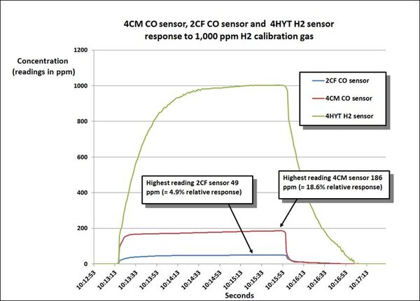
The following chart compares the relative response of the hydrogen nulled 2CF sensor and our standard 4CM CO sensor when the sensors are exposed to 1000 ppm hydrogen. The relative response of the 2CF sensor is less than 5%!
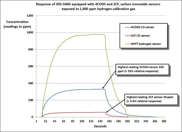
The second chart compares the performance of the 2CF hydrogen nulled sensor, and a standard 4 electrode dual channel CO / H2S “COSH” sensor exposed to 1000 ppm hydrogen calibration gas.
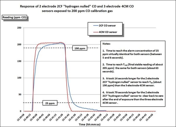
The third chart compares the performance of the GfG 2CF hydrogen nulled sensor, and a standard GfG 4CM CO sensor exposed to 200 ppm CO calibration gas. While the hydrogen nulled sensor takes a little more time to recover after exposure, the time to alarm is virtually the same for both sensors.
What other gases and vapors can have an interfering effect on CO sensor readings?
Although the internal organic vapor filter included in most CO sensors reduces the effects of interfering contaminants, once the filter is saturated, breakthrough can occur. Once breakthrough occurs the CO sensing electrode responds to a wide variety of interfering contaminants including alcohols, (such as methanol and isopropyl alcohol), solvent vapors, (such as toluene and MEK), combustible liquids, (such as kerosene and jet fuel), and unsaturated hydrocarbon gases (such as ethylene, propylene and isobutylene). Many CO sensors also show a significant response to nitric oxide, (NO). CO sensors also respond strongly to acetylene gas. Since the internal filter does not absorb acetylene, the sensor shows a very strong and immediate response to this gas. GfG Technical Note 2019, “G460 and Micro IV electrochemical (EC) toxic sensor relative response matrix” includes a chart listing some of the most common documented interferences for the electrochemical sensors used in GfG products.
Unfortunately, although CO sensors recover rapidly from exposure to hydrogen, it can take hours or even days for the sensor to recover completely after exposure to solvent vapor or acetylene. Although CO sensors are not usually harmed by exposure to low concentrations, exposure to very high concentrations of solvent or alcohol vapor can permanently damage the sensor. Never use alcohol or solvents to clean the instrument housing or sensor compartment area! Sample draw tubing or filters that are contaminated by solvent or exposure to heavy fuels (such as diesel vapor) should be discarded and replaced.
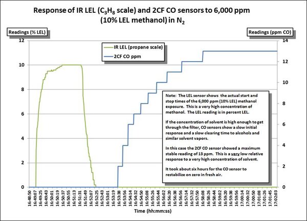
The following chart shows the response of an LEL sensor and a 2CF “hydrogen nulled” CO sensor to 10% LEL methanol (= 6,000 ppm). Note that this is a very high concentration of methanol! In the following chart you can see when the methanol starts to break through the internal filter in the CO sensor. The CO reading does not begin to rise until almost 4.5 minutes after the methanol exposure is ended. It took several hours for the CO sensor to finish stabilizing back on zero after the exposure to methanol. It should be noted that the final stable reading of 13 ppm for the 2CF CO sensor is extremely low compared to the response of most other CO sensors.
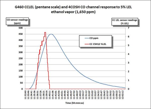
The following chart shows the response of the CO channel of a dual channel “COSH” type sensor for the measurement of CO and H2S to 5% volume (= 50,000 ppm) ethanol. Note that this is a very high concentration of ethanol! The red colored line on the chart shows the response of the LEL sensor. Because the COSH type sensor has a less robust internal filter, the relative response to the alcohol is quite a bit higher (450 ppm) than the response of the 2CF CO sensor in the previous example. It also takes a lot longer for the CO channel of the COSH sensor to recover after the exposure ends.
GfG supplies a substantial number of instruments equipped with the hydrogen nulled 2CF CO sensors for use in oil refinery applications. We receive very positive reviews for instruments equipped with this sensor. Please let us know if you would like to evaluate instruments that have been equipped with this type of sensor.
Thanks again for the question!