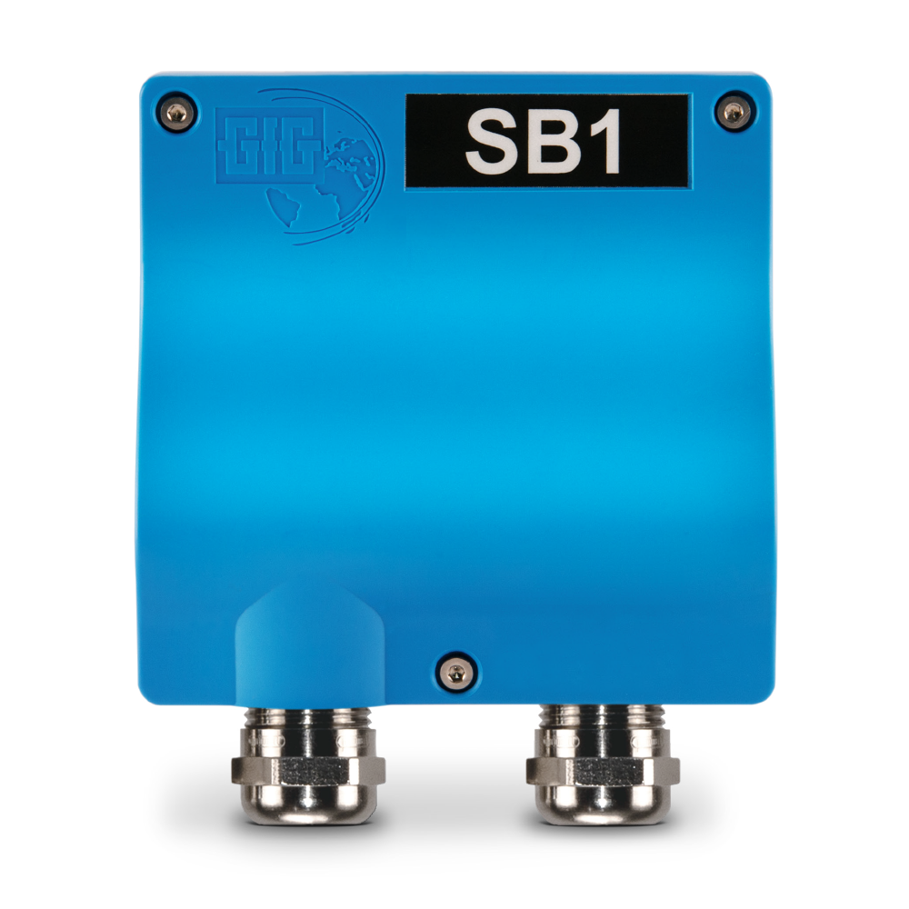
SB1 Safety Barrier
Two-channel safety barrier for intrinsically safe transmitters
Ex-Zone 0 environments place high demands on gas detection devices. They must not under any circumstances cause the ignition of a flammable atmosphere at any time during normal operation or even in the event of a fault. There are therefore limit values for voltage and current that must be observed. To connect an intrinsically safe transmitter in Ex zone 0, an intrinsically safe circuit must first be set up. A safety barrier is required if this intrinsically safe circuit is connected to one that is not. This is the purpose we developed the SB1 and its wall-mounting housing for.
In Ex-Zone 0 areas, it is critically important to ensure that the limit values for supply voltage and current are not exceeded at any time. To integrate an intrinsically safe transmitter into an existing 4-20 mA signal transmission, a safety barrier can be interposed between the two elements. The SB1 uses resistors to limit the input voltage from 24 V DV to a maximum output voltage of 21 V DC.
The SB1 safety barrier is installed outside the hazardous area. It transmits 4-20 mA signals between intrinsically safe and not intrinsically safe circuits. The intrinsically safe circuit originating from the safety barrier is routed into the Ex zone 0 area and supplies an intrinsically safe transmitter with an operating voltage of 21 V or less. Depending on the transmitter, it can be connected using a 2-wire or 4-wire cable. The supply module is connected to the controller with a 3-wire cable.
Key features at a glance:
- Transmitter supply module suitable for the intrinsically safe EC28 i, EC28 Di, IR29 i and IR29 Di transmitters
- Transmission of 4-20 mA signals between intrinsically safe and not intrinsically safe circuits
- 3-wire 4-20 mA lines to 2-wire or 4-wire lines in Ex zone 0
- ATEX certification: II (1)G [Ex ia Ga] IIC
- Also available as SB1 D with integrated 2.2" display
- Input voltage: 22 to 30 V DC (max. fault voltage 253 V AC)
- Output voltage: 21 V

